Friday, 6 December 2013

Architectural Design


Architectural Design of a software is basically identifying the subsystems of a software and making up a system and a framework to control and communicate between those subsystems.
It provides a link between requirement specifications and system design processes. The best part is already designed architectures can be re-used in new systems. Here I want to share something really interesting:
Missouri Department of Transportation (MoDOT) is developing a statewide approach to Intelligent Transportation Systems (ITS) implementation.
The six core ITS Program areas described in this architecture package are based on prioritization tools developed as part of the statewide plan. The prioritized areas are:
  •  Commercial vehicle operations
  •  Incident management
  •   Traffic control and monitoring
  •   Traveler and weather information
  • Transit management
  •   Maintenance and construction operations


Here is the link for further information: http://epg.modot.org/index.php?title=910.4_its_achitecture
Architectural Patterns is a term in architecture design. The concept of an architectural pattern has a broader scope than the concept of design patterns. It basically is description of good design practices which have already been tested and a description of when to use those patterns.
Now coming towards different types of architectures:
 As there are different architectural designs for buildings, there are several architectural designs for designing a software system.

Model View Controller:

In a typical application you will find these three fundamental parts:
  • Data (Model)
  • An interface to view and modify the data (View)
  • Operations that can be performed on the data (Controller)
MVC pattern in simple words:
The model represents the data, and does nothing else. The model does NOT depend on the controller or the view.
The view displays the model data, and sends user actions (e.g. button clicks) to the controller.
The controller provides model data to the view, and interprets user actions such as button clicks.


Let me give you example of a web application, here the view is the actual HTML page, and the controller is the code that gathers dynamic data and generates the content within the HTML. Finally, the model is represented by the actual content, usually stored in a database or XML files, and the business rules that transform that content based on user actions.


How things work in NustNews
The student editors and journalists cover the events and compile other news items and articles. The readers of the newsletter also provide feedback. The administration has also set some rules to allow the publication of a certain article or a report. Next newsletter is published after considering the suggestions and requests of the readers.
So here
Model is one who has data and rules.

View is one which is shown to user i-e the final newsletter.

Controller is one who interacts with user and update Model and influence model about what view should be shown to users.


Next Architectural Pattern I am going to discuss is layered architecture. This Architecture use different layers for allocating responsibilities of an application. These architectures can be used where security is an important aspect of the software.
As an example, think about the way a restaurant works. The main actors are:
  • The customer
  • The waiter
  • The Chef
They all have different responsibilities. Customer decides what to eat, eat the meal and pay the bill. The waiter takes the order and forward it to the Chef, he also clean tables and serve the bill. The Chef cooks or heat the food.
It makes sense to have the waiter taking the customer’s order and asking the Chef to cook the desired meal. No one ever let customer go to the kitchen. 
It is clear from the above example that layers have clear separation of responsibilities. We can replace a layer without effecting the other layers.
These architectures can be used where security is an important aspect of the software.

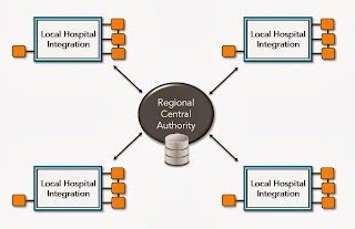
Architecture has a central database which is shared with all the other sub systems.
For example all the hospitals are linked to a central health authority.


Client Server Architecture as name indicate is an architectural design in which all the clients interact with the server and all the work is done in the server.

The Pipes and Filters architectural pattern provides a structure for systems that process a stream of data.
 To send a message from one application to another is not simple as it sounds. Normally you don’t just send a message. In enterprise world, there are lot of guidelines, concerns and lot other issues that you have to address from information exchange point of view. This is because of the very fact is “INFORMATION IS EVERYTHING TODAY”.
This pattern states what filters should be applied after the send has created the message and to the point that receiver has received the message. This concept makes use of PIPES which are transmission from one box to another and the boxes which are filters.


What have we learned?    \
  • Architectural Design     
  •  Model view Controller
  •   Layered Pattern      
  • Repository Pattern
  • Pipe and Filter Pattern


Modeling the Library


The week before I left my hometown to get back to Islamabad, my old school principle insisted me on paying a visit to my old school. I couldn’t refuse her. So there was I standing at the very place where my life began. It was a chilly Friday afternoon and the students had left for their homes at noon.  I was roaming from one empty classroom to another, bumping into teachers and exchanging greetings. Every nook and corner that I visited reminded me of my old friends and all the memories started playing like a movie in front of my eyes.
I stepped into our library. And just how a typical SE analyst would react, my instant reaction to the manual library management was ‘Damn! You still perform all the functions manually?’ The librarian turned back to respond, “Yes Ma’am!” recognized me and smiled warmly to welcome me. I walked ahead, exchanged few greetings and quickly resumed our discussion on the topic. When asked, he told me that the school library still records information about the books, the library members and transactions such as issuing and returning books in ledgers and registers.  Like other manual information systems, this system faces many data-related issues such as data redundancy, delayed retrieval of data, data corruption and inefficiency. As the number of members is increasing, maintaining manual records has become a difficult task for him. Searching for a particular record is equally difficult and time consuming. For instance, when he needs to know about the status of a book (whether it is issued or not), he has to manually traverse all the records one by one to find if that book has been issued/returned/not issued. Moreover, manually producing the reports for the issued books, the books in the library, members, or accounts becomes cumbersome because there are hundreds and thousands of records to go through.

This is one instance of the manual systems that you’ll encounter in your SE field and that you’ll have to find solutions for. To help us understand the functionality of such a system, analyse it and find software solutions for it, we take help of system modelling! One of the major components of the System Specification Stage of SDLC is the system modeling. Now the name sufficiently explains what it is about, modeling the system is the process of developing abstract views of an existing system or a proposed system. How about we find software solutions for my old school’s library system through system modeling? If you are interested, let’s go ahead!


Choosing a Model Type


To model our existing library system, we need to choose the model type that will help us clarify what the existing system does and use it as a basis for discussing the existing system’s strengths and weaknesses. This will lead us to understand the requirements for the new system. 


Each of these model types can be implemented using different UML diagram types. Don’t know what UML diagrams are? Don’t worry, we’ll explain. UML stands for Unified Modeling Language. <definition>
When you want to illustrate the operational context of a system, system boundaries are established to define what is inside and what is outside the system.


However, context models simply show the other systems in the environment, not how the system being developed is used in that environment. Process models reveal how the system being developed is used in broader business processes. These can be defined using UML activity diagrams.
In the interactive models, we can model either the system-to-system interaction or the component interaction using Use cases and sequence diagrams. Each use case represents a discrete task that involves external interaction with a system. Actors in a use case are people or other systems involved in those interactions. For example, the Use Cases for our Library Management system are Add a New Member, Edit Member details, Add a New Book, Edit Book details,  Issue a Book, Return a Book and Pay Fine.


Similarly, Sequence diagrams are part of the UML and are used to model the interactions between the actors and the objects within a system. (Learn more about Use Cases here and Sequence diagrams here)

In Structural modeling, you can use Class diagrams. Suppose we have decided to build an object-oriented system for our library. This system will consist of a number of classes such as Books and Members. The class Book shown below stores the attributes of all the books available in the library and the functions that can be performed.

The class diagram will show all the classes in a system and the associations between these classes. Lastly, State diagrams can be used to define Behavioral models. These are models of the dynamic behavior of a system as it is executing. They show how the system reacts to internal and external events.
So now, you have seen how many different ways are available to you to model a system using UML.
Planning the Proposed System
From activity diagrams to use cases, all the UML diagrams are easy to use and help you understand the working of a system and come up with the requirements for the new system.. In our existing system, the librarian recorded the details about the books and the library members and transactions such as issuing and returning books in ledgers and registers.  Using the system modelling, we concluded that our proposed system can be an object-oriented system.
Every new member fills a standardized form and gives his personal information such as his full name, address, contact number, CNIC number to the librarian. The librarian updates the database with the new member’s details using a member class instance and issues him a membership card and a member_ID. Similarly, Every new book purchased for the library is given a Book_ID and its details such Book Title, Author Name, Publisher, SSDN etc are recorded in a Books Relation using the Book Class instances. Whenever a member wishes to issue a book , the issue_book function is called. It checks the Members Relation to ensure that he has returned the previously issued book.

Final Words
See how easy it was?  For drill, you can study these UML diagrams further and come up with the rest of the functional requirements of the proposed Library Mgt System yourself.

What we learnt today:
  •  What is System modeling?
  •  What is Unified Modeling Language (UML)?
  • How does system modelling help the analyst to understand the functionality of the system?